Gate Programming
Gate Install
Follow the installation guide included with your gate. For any discrepancies, follow the manufacturers instructions.
Here are some pointers to demonstrate the gate configuration process.
Removing the protective cover
https://youtube.com/shorts/kGReBivaUGs
Connecting AC power to the unit

Plug in the network cable
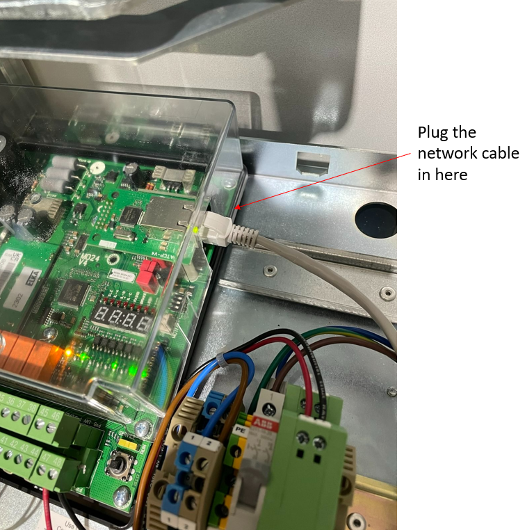
Terminating the Inductive Coils
Follow the installation manual. Reminder, inductive coils should be installed in the ground with the black side up.
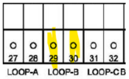
Loop A is the "arming loop" and is not used with the pay station.
Connect Loop B (safety loop) wires as shown:
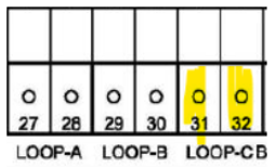
Connect Loop C (merge loop) wires as shown:
Programming the IP address
How to access the programming menu at the gate:
To program the controller and to set the operating parameters a four-digit 7-segment-display and a joystick (1) are available on the control board. The joystick has the functions UP, DOWN, and PROG when pressed in.
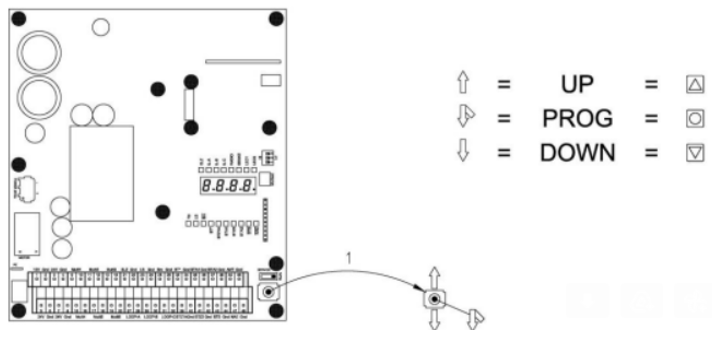
(This video shows a gate being programmed with a 10.1.83.23 IP address) Follow the steps in the installation guide to perform this operation. This video just shows you how the selector button operates. You need to program the gateway and mask as well, which is not shown in the video. Follow the installation guide.
The gateway for an IP address of 10.1.83.23 will be 10.1.83.1.
If you were programming an IP address of 10.2.25.45, the gateway would be 10.2.25.1 (the last number is a 1, the rest of the numbers are the same).
The mask will "always" be 255.255.255.0
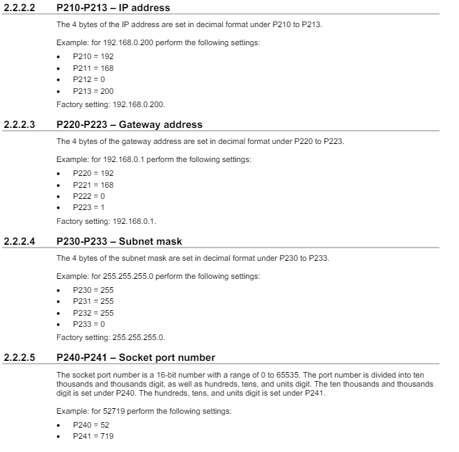
Program the IP, Gateway, Mask, and confirm the Port
Set the IP address based on your network sheet. Program the port to 52719.
Programming the Loops
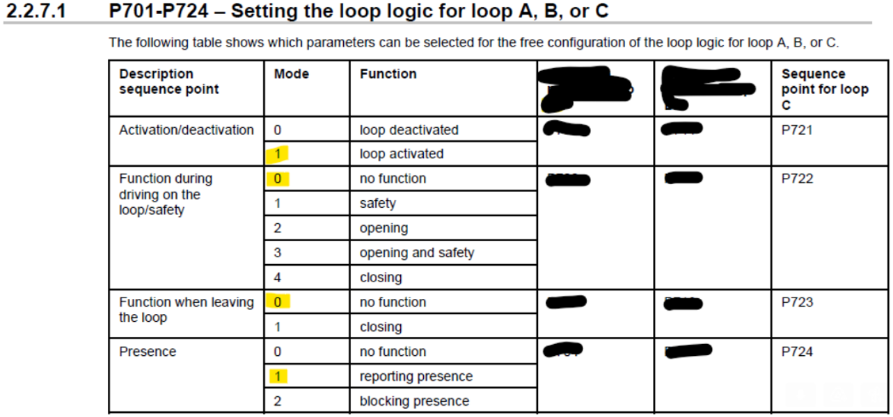
Push the joystick “in” and wait until the display changes to P100. Then tab UP and release until you see P700, push joystick “in” momentarily and the display should change to P701, toggle up to P711. Select by pushing the joystick “in” momentarily and you should see a “0” on the display (“0” in this case means that loop B is disabled). To enable change the number to 1 and confirm by pushing the joystick “in”. Then you get to the next setting P712. The settings are explained below. Follow the same steps until all settings are complete. Once all settings are complete, select down until P7PP shows and push the joystick “in”. You should now see P800 on the display. Then press DOWN until PPPP shows and then press joystick “in”. The controller will now rest and go back into operation mode.
Setting for Loop A: (Arming loop) - we do not use loop A at the pay station. Advance to setting P711 for loop B.
Setting for Loop B: (Safety loop)

Setting for Loop C: (Merge Loop)
Set the frequency range
Adjust the frequency range of adjacent lanes to opposite frequencies. See 2.2.6.3 in the installation manual.
If 2 lanes, set Lane 1 = High, Lane 2 = Low
If 3 lanes, set Lane 1 = High, Lane 2 = Low, Lane 3 = High
If 4 lanes, set Lane 1 = High, Lane 2 = Low, Lane 3 = High, Lane 4 = Low
If 5 lanes, set Lane 1 = High, Lane 2 = Low, Lane 3 = High, Lane 4 = Low, Lane 5 = High
Configure all loops in the lane on the same frequency using the dip switches.
Note, the installation manual and the board labels are opposite in terms of loop assignment (3 is A versus 3 is C). The important point is that all loops connected to the same gate are on the same frequency and adjacent gates/loops are on the opposite frequency.