Wash World Razor - pay station interface
Documentation provided courtesy of David Melhorn from Pure Wash Solutions
Sealevel I/O wiring interface
INPUTS | TERMINAL | FROM RAZOR |
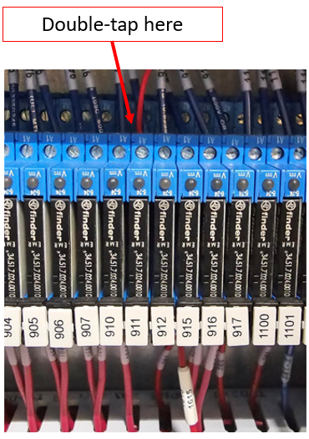
| 1 – Wash Status | 1 |
911/okPos@output crd
|
2 – Gate loop signal (if used) | 2 | |
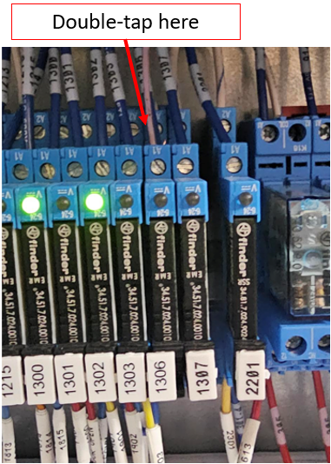
3 – Out of Service | 3 |
1306
|
4 – n/a | 4 | |
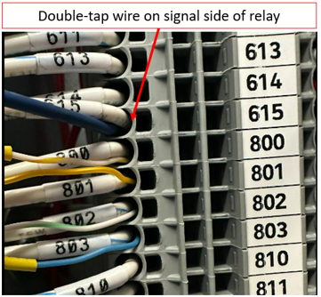
5 – Photo Eye | 5 |
615 (UB photo eye)
|
OUTPUTS | TERMINAL | TO RAZOR |
1 | 1 N.O. | 800 |
2 | 2 N.O. | 801 |
3 | 3 N.O. | 802 |
4 | 4 N.O. | 803 |
5 | 5 N.O. | 810 |
6 | 6 N.O. | 811 |
7 | 7 N.O. | 812 |
8 | 8 N.O. | 813 |
Notes:
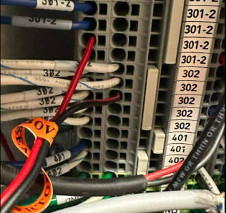
1) Connect the 24VDC Negative from 302 to the Sealevel power input on the left side power block on the rear GND and to the common terminal on the first input block on the front of the Sealevel. Also connect 24VDC Negative to wash output block commons.
2) Connect the 24VDC Positive from 301 to the Sealevel power input on the left side power block in the 9-30 VDC and to common terminal on 2nd input block.
3) Connect “Wash Status” signal wire to the signal (coil) side of the relay.
4) Set Dencar Customer Management Portal Sealevel to 2-wire out of service signaling.
5) On the Razor controller, set the wash status signaling to “Wash Done” signaling.


