RFID Installation & Setup
RFID Components
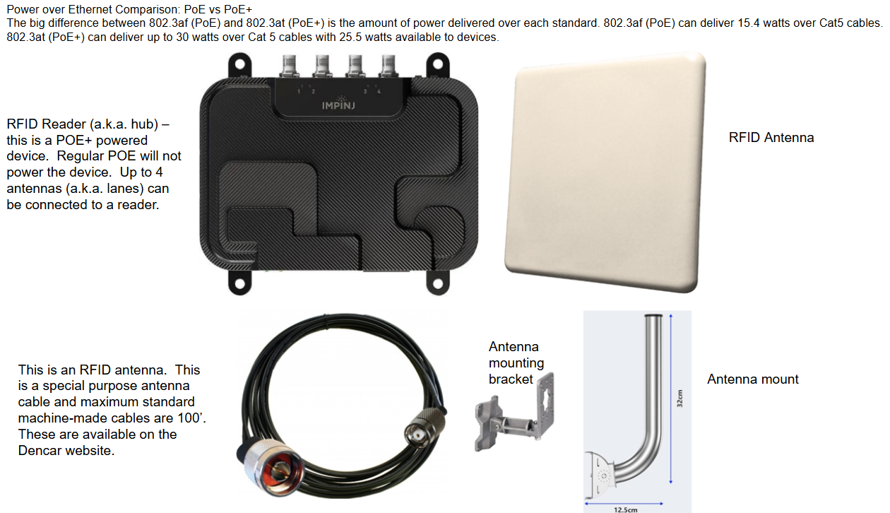
The RFID equipment will be pre-configured. If you would like to review the RFID settings, login to the Customer Management Portal (CMP), and go to the RFID Scanner component setting on the appropriate device. Please see the following definitions and image.

NOTE: for tunnels utilizing the Dencar lane manager, the lane manager controller is the device that controls the setup of the RFID Reader. The RFID Scanner component setting is also visible on the pay station controller, but will not have any impact on a tunnel configuration using a lane manager.
rfid:ip – static IP on the reader
rfid:power – (10 - 33 decibels per milliwatt a.k.a. dBm) this is the amount of RF energy emitted by an RFID reader in order to energize RFID tags in the area. A larger number is more power.
rfid:sensitivity – (-19 - -90) basically a measure of how sensitive the RFID reader is when detecting RFID tags. Most fixed RFID readers have a max receive sensitivity between -84 dBm and -92 dBm and these values can be configured just like reader transmit power. Users can actually control receive sensitivity by inputting an RSSI value range that they would like to see. For instance, a user can tell the reader to only report RFID tags with an RSSI value between -30 and -55. With this set parameter, the RFID reader would still read all the RFID tags in the area, but it would only report tags within the set RSSI value. Configuring a reader’s receive sensitivity is comparable to placing a filter on RFID tag reads. We don’t generally use this setting.
rfid:threshold – this is the activation level of the RFID sticker. An RFID sticker must have a reading below this value to activate the car wash. Low values are strong. Higher number values are weaker signal strength. In this case, the signal must be <= 60 in order for the car wash to activate.
rfid:timeout (seconds) – this is the clear time after a tag is no longer read. For example, if an RFID tag is under the antenna and is being read, it will only fire the wash 1 time. If the RFID tag leaves the read area, it will start a countdown of this value. If the RFID tag returns to the read area during this countdown, it will not activate the wash. For example, a car pulls up to the RFID reader and activates the wash. For whatever reason, the car pulls forward out of the read area, but then backs up into the read area within the 120 seconds. The RFID will not trigger another wash.
Applying Changes
Once these settings are applied in the CMP, they are pulled down to the Nuc attached to the RFID reader. If you make changes on the CMP, reboot the Nuc to download and apply the changes.
HOWEVER, during implementation and testing, the changes can be made directly on the Nuc Control Console. This makes testing and making changes quick and easy. Once the RFID reader is dialed in from adjusting the settings on the Control Console, be sure to copy those settings into the CMP and then reboot the Nuc. Ensure the correct values were saved in the CMP and then downloaded to the Nuc by looking at the Control Console settings.
Interesting Expanded Reading
RFID Transmit Power
RFID transmit power is the amount of RF energy emitted by an RFID reader in order to communicate with RFID tags in the area. RFID transmit power is measured and specified in decibels per milliwatt, or dBm. A reader’s transmit power is configurable from 0 dBm up to its max power level, which is usually between 27 dBm and 31.5 dBm. An RFID reader’s transmit power can easily be converted from dBm to milliWatts or even to Watts via a table like the one available here.
During RFID testing, a reader’s transmit power can easily be changed and configured in order to control the read distance at which an RFID system will read RFID tags. Reducing or increasing a reader’s transmit power is not a simple change because transmit power is measured on the logarithmic scale. For example, if you reduce a reader’s transmit power from 30 dBm to 27 dBm, you are effectively reducing your reader’s power by 50%. When experimenting with reader transmit power, it’s important to remember that changing your transmit power by 3 dBm will half or double the power at which your RFID system currently resides.
When you raise or lower the transmit power, you are basically just changing the amount of power being pushed out through the RFID antenna to read tags at a further or shorter distance. A lower transmit power can be important for defining a read area and avoiding stray tag reads. Be sure to experiment with different transmit powers during RFID testing in order to understand your system's needs.
RFID Receive Sensitivity
RFID Receive Sensitivity (Rx Sensitivity) is basically a measure of how sensitive the RFID reader is when detecting RFID tags. Before we dive into receive sensitivity, it’s important to first understand the concept of RSSI or Received Signal Strength Indicator.
In a UHF RFID system, readers send an interrogation signal to a nearby tag, which responds in turn via backscatter. The reader analyzes the response and reports the tag’s data along with the signal’s RSSI. RSSI, or Received Signal Strength Indicator, is a measurement of the power received from the returned signal from an RFID tag when interrogated by a reader.
When a reader reports a tag’s RSSI value, it is effectively reporting the power level of the tag’s backscattered response signal as it relates to the power level of the reader’s initial transmission signal.
An RFID tag’s RSSI value can range anywhere from - 30 to -92 dBm and the closer the RSSI value is to 0, the better the signal. The more sensitive the RFID reader is, the more likely the reader is to read tags with weak signals. Most fixed RFID readers have a max receive sensitivity between -84 dBm and -92 dBm and these values can be configured just like reader transmit power.
Users can actually control receive sensitivity by inputting an RSSI value range that they would like to see. For instance, a user can tell the Impinj R700 to only report RFID tags with an RSSI value between -30 and -55. With this set parameter, the RFID reader would still read all the RFID tags in the area, but it would only report tags within the set RSSI value. Configuring a reader’s receive sensitivity is comparable to placing a filter on RFID tag reads.
When to Configure Reader Transmit Power vs. Receive Sensitivity
In most RFID systems, it is recommended to test different settings for both transmit power and receive sensitivity in order to create the ideal read zone. However, for the car washes, we typically just use the transmit power setting.
Antenna Placement
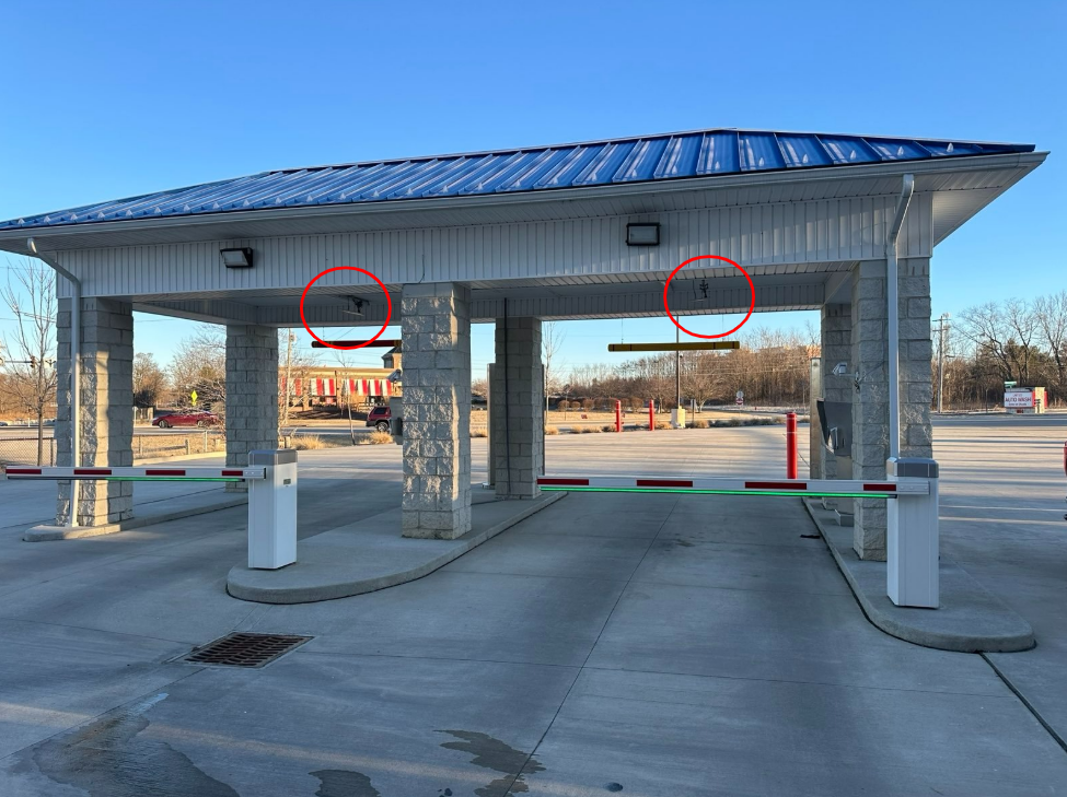
These are the RFID antennas. Note how they are angled slightly away from each other. If this was a 3-lane tunnel, the center antenna would point straight down, and the outer two antennas would angle outward as shown in this picture.
NOTE: on an IBA, there is 1 RFID Reader and 1 RFID antenna per bay. On a Tunnel configuration, there is generally 1 RFID reader with 2 or 3 antennas (1 antenna per lane). On a tunnel, the RFID antenna cable needs to be run back to the RFID reader. Typically, the RFID reader will be in lane 1 whereas RFID antennas in lanes 2 and 3 need their RFID cabling run back to lane 1 (assuming the RFID reader is in the lane 1 pay station).
RFID antenna angle example
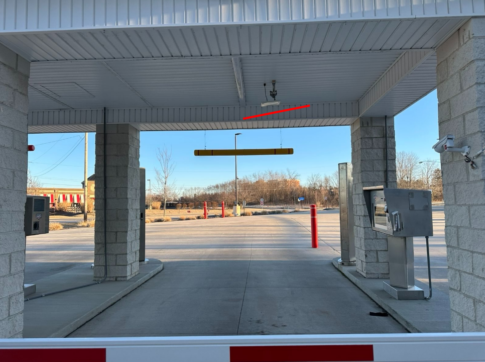 Example angle shown via the red line.
Power Example #1
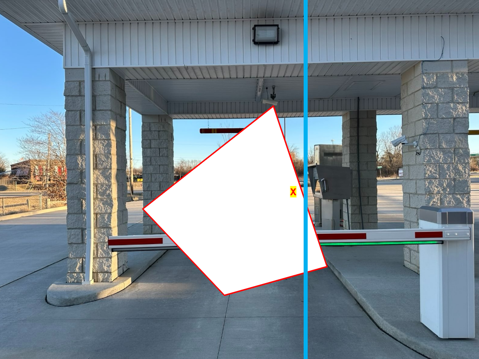
This image shows lower power compared to image 2. The red outline area is the RFID energy cone. The RFID tag needs to be in this area in order to be read. This X represents an RFID tag. Note on the next image how the red outlined area is further away from the antenna.
Power Example #2
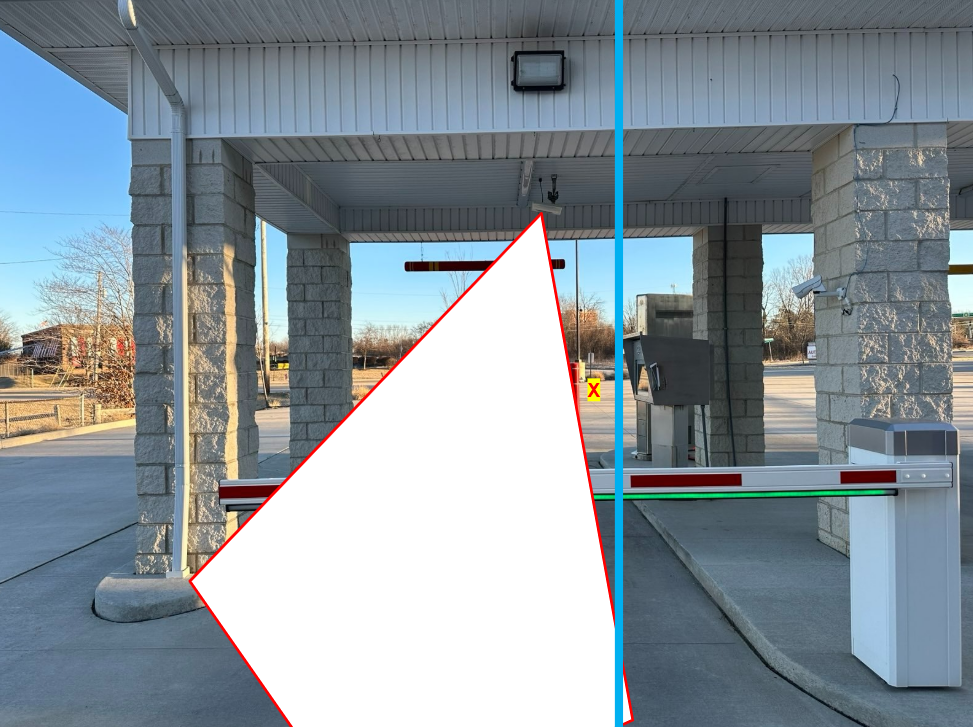
This image shows higher power compared to image 1. The red outline area is the RFID energy cone. By increasing the power on the Reader, the energy cone is pushed further away from the antenna. This means the energy cone is narrower closer to the antenna and wider further away from the antenna. In this example, by increasing power, the RFID energy cone is now narrow where the RFID tag is located (see the X) and the car wash would not activate.
Control Console - IBAs only (no Lane Manager configuration)
The following is only for 1:1 (IBA) RFID deployments.

This is a view of the Control Console on the Pay Station showing the status of the RFID.
RFID Enabled – this is a toggle on/off just like the pay station in service button or the Bar Code Scanner button.
The power and sensitivity shown here is what is downloaded from the CMP. During install and testing, the technician can change the power and sensitivity settings from the Control Console for fine tuning the settings. However, these settings are not saved. The settings must be entered in the CMP and then the pay station restarted to download the settings from the CMP.
Auto Import should generally be left off. This is a feature for a customer to import the tags on the vehicles when they don’t have the ability to do a bulk import. For example, if we might deploy our RFID reader months in advance of a pay station conversion to read and import all the RFID tags that come through a wash during a multi-month period.