General Installation Overview
Preface
Stainless steel is a group of iron-based alloys that contain a minimum of approximately 11% chromium, a composition that prevents the iron from rusting and provides heat-resistant properties. Stainless steel’s resistance to rusting results from the presence of chromium in the alloy, which forms a passive film that protects the underlying material from corrosion attack and can self-heal in the presence of oxygen. Resistance to corrosion and staining, low maintenance, and familiar luster make stainless steel an ideal material for many applications where both the strength of steel and corrosion resistance are required.
When applying stainless steel fasteners, ‘cold welding’ (also known as seizing, galling or fretting) may occur during assembly. In this case, the threading sticks together until no further movement is possible, which may lead to the fracturing of screws during tightening or disassembly. The seizing effect may cause problems during disassembly, perhaps that the fasteners just do not loosen or break when excessive pressure is applied.
Dencar equipment is built from stainless steel designed to provide a lasting impression on your customers over time.
Moral of the story: Do not over tighten stainless steel nuts and bolts. Use an anti-seizing lubricant on all fasteners.
Installation Support
Please set proper expectations during the installation and turn-up process. Turn-up support should be scheduled as a planned activity with as much advance notice as possible. Distributors and installers may install after hours or on weekends, but primary turn-up support from Dencar is Monday – Thursday from 8:00AM-5:00PM Eastern. It is highly recommended that a new install is not started on a Friday.
Site planning and preparation
- Before you begin, plan your process. Read all of the installation process documentation before you begin. Unbox all your equipment and supplies and inventory everything. Get a feel for what you are working with and identify where you will place everything. Map your site and create a plan. Review your plan with the Dencar team so we can help with any questions or gotchas before you begin.
- The Denpay platform is built around an Integrated Sales Experience approach. This means that all equipment is designed to work together to facilitate an entire onsite (and offsite through the Dencar Marketing Platform) marketing experience to your customers. Dencar equipment lines include:
- Pre-purchase Menu Board.
- Pay station with license plate reading (LPR) functionality.
- Post-purchase Marketing Board (Wait/Go Sign).
- In-Bay Directional Signage.
- Central vacuum systems.
- Coin boxes.
- Relay activation for self-serve, vacuum, ancillary profit centers.
The layout of this equipment follows a natural flow to focus your customers’ attention and drive monthly wash pass sales.
- Consider the following configuration guides when planning your site layout.
- All Dencar equipment is network connected. This means all equipment needs a dedicated Cat 5e or better network connection at no greater distance than 300 feet. If there are runs greater than 300 feet, we need to place network switch equipment along the path to limit the network segments to less than 300 feet. The placement of this secondary network equipment is referred to as an Intermediate Distribution Frame (IDF). This configuration must be discussed with Dencar prior to order as IDF equipment is not part of a standard order. Network cabling should always be run in conduit separate from electrical runs. These devices need dedicated network connections:
- Pay station controller (located inside the pay station).
- License plate reading camera (wherever located).
- Wash Equipment I/O Interface (Sealevel, located in the control cabinet).
- Menu board (wherever located).
- Menu board I/O Interface (Sealevel, located in the control cabinet) – Only required if deployed in stand-alone mode i.e., without a Dencar pay station.
- Marketing board – wait/go sign (wherever located).
- Marketing board I/O Interface (Sealevel, located in the control cabinet)
- In-Bay Directional sign (wherever located).
- In-Bay Directional sign I/O Interface (Sealevel, located in the control cabinet).
- Coin boxes and/or wired relay activation units.
- The Dencar network will replace the customer’s existing network if one exists. Wiring for existing network equipment should be run to the Dencar network patch panel.
- All network runs to be terminated with RJ45 connectors and tested for full continuity.
- If wired network connections are unavailable, a WIFI network can be considered but should be discussed prior to making a purchase decision. WIFI introduces additional variables and performance needs to be considered for each connection.
- If wired network connections will be run near electrical runs, it is recommended to utilize shielded twisted pair cabling with proper grounding.
- Requirements specified in local electrical and building codes must be followed and shall take precedence over the guidelines provided within this document. All wiring and equipment should be installed by a licensed electrician.
Conduit Runs & Power Requirements
- Typical installations will include power conduit, network conduit, and gate control conduit. Do not combine these runs into shared conduit. Consult your gate control manual to determine the type of power and control wiring required for the gate. The Dencar design utilizes a home run model for all network wiring back to the network switch in the equipment room. If this is not achievable in your site design, discuss network configuration prior to order placement. The pay station and gate should be on separate power circuits. The LPR camera utilizes Power over Ethernet (POE) supplied from the central network switch. If this is not achievable in your design, discuss this prior to order placement for alternative equipment. Dencar supplied gates are network controlled, not relay wiring, meaning the gate requires a dedicated network run from the gate to the network switch.
- The Dencar Pay Station requires a dedicated 20-amp circuit.
- There is sufficient space in the Dencar Pay Station base to deliver the conduit landing to this point and extend to the gate, and license plate reading camera. See sample diagram Image 1.
- The landing base of the Dencar Pay Station (Model S2 and Model O and Model EP21) has a 6” diameter hole to receive conduit.
- The Dencar Menu Board should receive a dedicated 20-amp circuit and separate network run.
- The Dencar Marketing Board should receive a dedicated 15-amp circuit and separate network run.
- The Dencar In-Bay Directional Sign should receive a dedicated 15-amp circuit and separate network run.

License plate reading (LPR) – a short primer
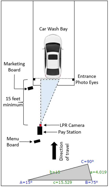
- Aside from an unobstructed view of the license plate, there are some key facets that one should consider for optimal license plate reads. License plate cameras are optimally situated when their viewing angle is less than 15-degrees. This is important when considering your camera placement. Accuracy degrades significantly beyond a 30-degree horizontal or vertical angle. If possible, mount the camera high enough and angled slightly downward to avoid direct taillight glare. The diagrams below utilize a 15-degree optimal design with associated minimum measurements.
- An average car width is 6 feet 3 inches. License plates are typically centered in the rear of the vehicle or offset to the driver side (USA). When placing an LPR camera at minimum distance, it should be placed on the driver side of the vehicle.
- A vehicle position trigger point is used to capture an LPR picture. This can be a photo eye or inductive coil signal. Consider the placement of your trigger point and the position of the LPR camera. Note the trigger point can be an existing photo eye or inductive coil. The trigger point does not need to be a dedicated relay as the wiring can be double tapped.
- The LPR camera has an optical zoom and can be placed beyond the minimum distances shown in the following examples.
Sample license plate capture at 15 feet
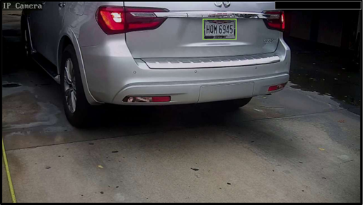
License Plate Read: HQM6945
License Plate Confidence: 94.44%
This sample shows an above average size vehicle at 15 feet approaching a 30-degree angle. You can easily imagine the placement of a small sedan or a full-size pickup truck within this picture.
Positioning the pay station and supporting equipment
In-Bay Automatic – Pay station, No gate, No stack.
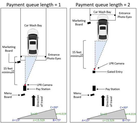
- Queue management can be held within the Denpay point of sale or the Denpay point of sale can feed a queue management held within the PLC.
- A traditional in-bay automatic has a pay station directly in front of the entrance to the car wash. There is no gate and there is no physical car stack between the pay station and the car wash building. The LPR capture point is typically the entrance photo eyes.
- This image shows the typical placement and minimum distance for the LPR camera and the LPR image capture trigger point.
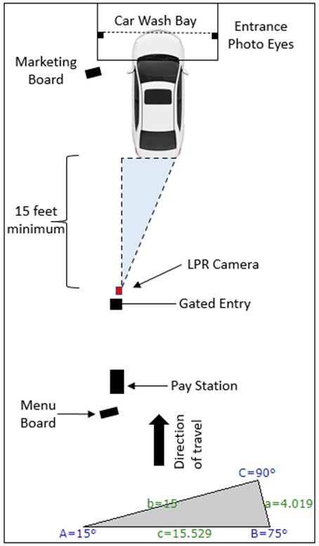
In-Bay Automatic – Pay station, Gate, 1 car stack.
- Queue management can be held within the Denpay point of sale or the Denpay point of sale can feed a queue management held within the PLC.
- A single car stack with a gated entry provides multiple options for LPR capture. The most common trigger point will be the entrance photo eyes. Note in this diagram (Image 3) we show the image capture when the front of the vehicle enters the photo eyes whereas the typical no gate capture triggers when the vehicle leaves the entrance photo eyes. Either option is supported and the LPR capture point is a simple configuration. This holds true for inductive coil configurations shown further on in this guide.
- This example shows a post gate placement of the LPR camera. Keep in mind that all examples show the minimum distance and less than 15-degree viewing angle. A 5- or 10-degree viewing angle is better than a 15-degree angle. While a greater than 15-degree viewing angle degrades the quality of LPR capture, Dencar’s Vehicle Identification Automation (VIA Guard) technology can help compensate for less-than-optimal designs, but the operator will be engaged in more manual review.
In-Bay Automatic – Pay station, Gate, Multi-car stack.
- Queue management can be held within the Denpay point of sale or the Denpay point of sale can feed a queue management held within the PLC.
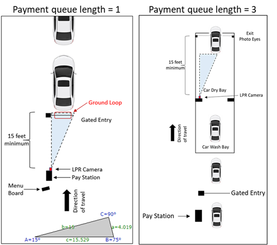
- A third configuration option utilizes a gate inductive coil as the trigger point for LPR capture. Measured distance and unobstructed view are primary considerations for this design placement.
- Note that the measurement shown in image A is as the vehicle leaves the inductive coil and the gate signal triggers a close gate message. The typical inductive coil wiring is past the gate center measurement.
- Image B shows an LPR camera placement before the pay station. This is a highly effective design when the gate placement does not permit the needed 15 feet of distance from the pay station LPR camera placement to the inductive coil. Note that there is a small risk of an aggressive follow-on driver obstructing the view between the LPR camera and the inductive coil trigger point. However, the Dencar VIA Guard technology helps mitigate this risk through exception reporting.
- Image C shows an LPR camera placement on the pay station installed on an entrance with a left-hand turn. This is not an advisable configuration, but the results have been surprisingly accurate. VIA Guard technology enhances the LPR experience to eliminate impact to your customers.
Image A
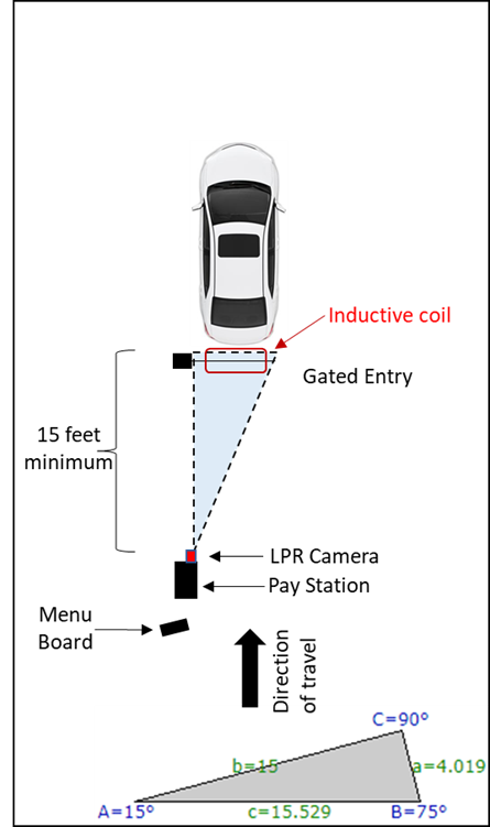
Image B
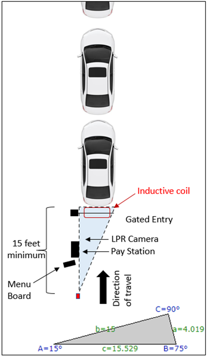
Image C

License Plate Read: GZA5288
License Plate Confidence: 93.69%
This sample shows an installation where the pay station and gate were installed on a left-hand turn. The camera is installed on the pay station and a trailing edge inductive coil trigger capture point was used. All specifications are outside of the recommended design. This is not an advisable configuration, but the results have been surprisingly accurate.
Long bay / Drying room camera placement
- LPR cameras can be placed in any location where the car flow is controlled and consistent. While typical LPR camera placement is near the entrance to the car wash, an interior pre-exit-based placement provides optimal LPR characteristics.
- The primary advantages of a “drying room” based placement are that the LPR occurs on a clean license plate (no snow or dirt coverage issues) and lighting is controlled. This makes for a consistent read experience.
Sample drying bay layout

Sample drying bay picture
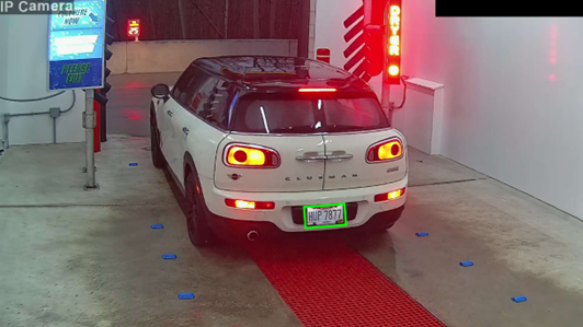
License Plate Read: HUP7877
License Plate Confidence: 94.79%
This sample shows an installation where the LPR camera is installed in the drying room of the car wash. The license plate is clean (no snow covering and no dirt) and the lighting is the same on every picture. This is an ideal configuration for LPR capture.
- The payment queue length is set within the Customer Management Portal (CMP) under the Component Settings for the Camera.
- The payment queue length is the quantity of payments that can be held before the vehicle reaches the LPR capture point. The vehicle at the pay station is counted as 1, any vehicles after the pay station, prior to the LPR capture point, are counted as 2 through X.
- Setting the payment queue length to zero will post payments to the Customer Management Portal immediately without waiting for the LPR capture input.
- Sample layouts with payment queue length are as follows.
- Please note, drying bay configurations often result in mismatched pictures between driver and vehicle as a result of unexpected inputs (walking through a photo eye, drivers pull forward and back up, etc.). There are a lot of variables. The most reliable configuration for payment queue posting accurately is a configuration of 1.
Sample queue length layouts
Anchoring the Equipment
- Lock nuts in place using a threadlocker (Loctite Blue 243) once all leveling adjustments have been made.
- For wet-set concrete, it is recommended to use 1/2-20 UNF J Anchor Bolts set at a minimum of 6” above the concrete. Excess thread height can be cut off after the mounting bracket has been installed.
- For existing concrete, it is recommended to use CONFAST 1/2″ (Inside/Screw 1/2″-13 Diameter Threads) 304 Stainless Steel Drop-in Anchors. Once anchors are installed, use stainless steel threaded rod cut to desired length and use a copper infused anti-seize lubricant.
- For drop-in anchors, follow manufacturer’s guidelines:
- The anchor is made from 304 Stainless Steel. This anchor is designed for use in Concrete only and should never be used in block or brick base material. The anchor is designed for use in a Wet environment. The anchor requires a 5/8″ hole to be drilled in the base material (Concrete only).
- The hole should be drilled with carbide tipped bit that meets ANSI standards and used in a hammer drill.
- The minimum anchor embedment into the concrete is 2″. Therefore, the anchor must be installed so that a minimum of 2″ of the anchor is embedded into the concrete.
- Each anchor must be spaced a minimum distance of 6-1/4″ from each other when measured center to center.
- It is especially important not to install the anchor any closer than 3-1/8″ from an unsupported edge of the concrete.